How Easy is It for Red Lighting Wires to Blow
Replacing and Wiring a Light Fitting
This DIY guide provides Information on replacing and wiring a light fitting in your home including safety tips, two and three way lighting and fitting ceiling lights. This project also includes a light fitting diagram for a ceiling rose.
Warning: To complete electrical works you must comply with Electrical Regulations – Click here for more information.
Please also see our project on the New Wiring and Cable Colours.
The first rule here is, when wiring a light fitting or changing a light fitting, if you are in any doubt whatsoever, get an electrician – Electricity kills.
Please remember when attempting any electrical installations at home that you are obliged to get the completed job tested by a fully qualified electrician and obtain a minor works certificate. Failure to do this may render your house insurance invalid and you may have difficulty selling your home. Please also see our project Part P Building Regulations
See also, our lights and switches, our wiring in wall lights and also our electrical safety projects.
Common Mistakes When Fitting Light Fittings
The most common mistake made by people wishing to change their light fittings, eg bulbs for spotlights etc, is that they take down the existing light and ceiling rose without marking or taking note of where all the cables went.
Then comes the mistake, they join all the reds together, then all the blacks, earths are connected, switch turned on and "PING" the fuse blows or the trip-switch flicks off. Why?
Well, 99% of the time one of the black wires belongs to the switch cable that controls that light. Both wires, red and black (or brown live and blue neutral with new wiring colours), are live wires in a switch as you will see a little later. The black wire for the switch should have a little bit of red tape around it, or a little red sleeve on it. This makes the job of identifying the switch cable easy.
If there is no such labeling, an indicator is necessary.
Make sure you mark any wires and cables yourself when necessary.
How Does the Lighting Work in Your House?
Not as big a deal to sort out, but first it is important to understand how the lights work in your house. The diagram below shows the circuits involved. (Please note some older houses may be wired differently in junction boxes which will be located under the floor/loft, the principle is the same).
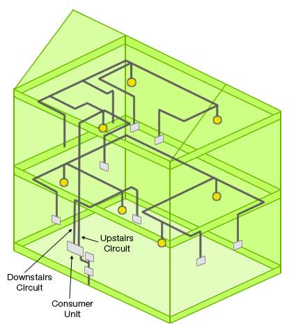
lighting circuit found in a house
Power comes into the house to your fuse board or consumer unit. The lights are fed from this via (generally) two circuits. One for upstairs lights and one for downstairs. Both of these circuits should be on 5 amp fuses or MCB's (Miniature Circuit Breakers). This fuse, in theory, allows up to 12 100W bulbs to be used on that circuit, in practice no more than 8 are normally fitted.
The cable runs from the consumer unit, to the first light fitting in the ceiling of that floor, it enters the ceiling rose where it is looped in and out to feed the next light, etc etc.
At the same time a cable is connected into the ceiling rose to the switch that controls that light. With ordinary "one way" lighting, ie one switch controls only one light, the diagrams and explanations below apply. For two and three way lighting diagrams, which can be identified by additional yellow and blue wires within the lighting switch cables, follow the link.
Removing an Existing Light Fitting
When you have removed your existing light fitting and are faced with a mass of cables hanging out of the ceiling, life is a little daunting…But it is not as complicated as it looks.
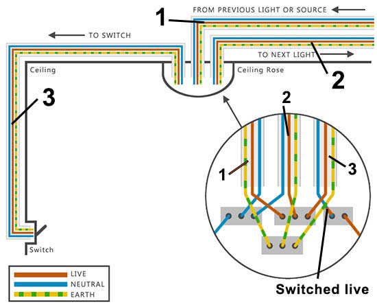
Ceiling rose wiring diagram
You can see from the above that the loop wires (all wires in this kind of lighting circuit belong to the lighting "loop") are connected to terminal blocks. The live terminal is fed from the consumer unit and in turn gives live power to the other cables in the circuit, in this case cable 1 supplies the live power from the source or previous light, where it is taken by cables 2 and 3.
The neutrals of cables 1 and 2 are joined together in the neutral terminal block, the left terminal block in this case. This is where the neutral side of any light fitting will go. Cable 3 is the switch cable and as you can see more clearly from our diagram in lights and switches this cable interrupts the live flow with a switch. The switch simply cuts off the live current.
The brown and blue (or red and black with old wire colours) wires either side of the ceiling rose are the live and neutral feed directly to the light fitting, in this case they would appear as a flex.
When you have removed your existing fitting, you will need to know which wires go to the switch. Hopefully, as explained above, they will be labeled with either a piece of brown (or red with old wire colours) tape on the blue (or black) wire, or a small brown or red sleeve.
If you have no indication whatever of which three (brown, blue and earth) wires form the switch cable then you will need a circuit tester. To use this device is not difficult but you must turn all the lighting power off first and take out the fuses so they cannot be turned on by accident.
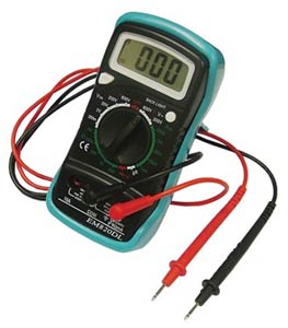
Pocket multimeter available from our superstore
Identifying the Wires to the Light Switch
When the power is OFF and fuses out, turn off the light switch, ie make sure the switch is in the off position. Now it is a case of trial and error.
Hold the red and black terminals of your circuit tester to a brown and a blue (or red and black) wire that appear in the same cable. (Using the diagram above, this would mean either cable 1, 2 or 3. Then turn on the light switch (With all power off to the lighting circuits, there is no power to the switch).
If you have connected to the switch cable, the circuit tester will indicate that you have completed a circuit. If not , it will not move and you try the next set of brown and blue wires that are in a cable together. When you have identified the switch cable, mark the blue with some brown insulating tape and even put a piece of tape around the cable sheath so there can be no mistake.
Fitting Your New Light Fitting
Ideally, your new light fitting will fit over your ceiling rose and there will be no need to take it apart. The live and neutral of the new fitting simply connect to the live and neutral the old fitting was removed from. If this is not the case, then we will, need to adapt the rose connections to suit the fitting you have.
The easiest way to do that is by making all existing connections into cable connectors (minimum 5 amp) or a junction box, as shown below. The live cables will be joined as they were in the ceiling rose, as will the neutrals, and finally, but very importantly, the earths.
With these connections made, the live, neutral and earth from your new light fitting can be connected. The base of most modern light fittings is big enough to conceal these new connections but occasionally one has to make a larger hole in the ceiling to push the junction box into. The light fitting is then screwed up as normal.
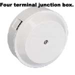
4 terminal junction box available from our superstore
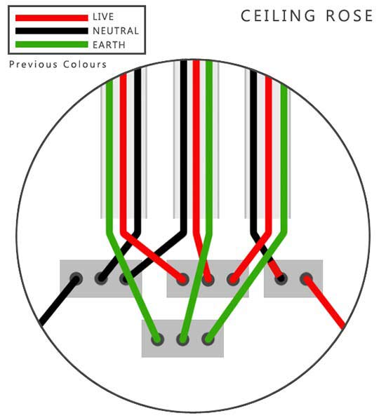
Ceiling rose diagram for old wire colours
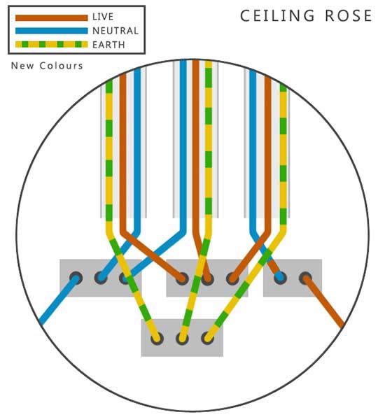
Ceiling rose diagram for new wire colours
Using the same numbers for the cables as above in the ceiling rose diagrams, this is how the junction box would be wired to replicate the circuit. The red and brown tape on the switch live side of the circuit in each scenario image above is shown. Good luck with your project and remember to stay safe.
Electrical Wiring Domestic Book available on Amazon
Wiring and Lighting Book available on Amazon
eldridgerobsits63.blogspot.com
Source: https://www.diydoctor.org.uk/projects/replacelightfitting.htm
0 Response to "How Easy is It for Red Lighting Wires to Blow"
Post a Comment